High-level representations of common NoC Topologies

SoC Interconnect Fabric: A Brief History from Buses to the NoCs of Today and Tomorrow

High-level representations of common NoC Topologies

The Evolution of SoC Interconnect Fabrics

To better understand how NoCs address these challenges, it’s helpful to trace the evolution of SoC interconnect fabrics through three eras: buses, crossbar switches, and networks-on-chip. These are briefly introduced below.

Phase 1: Buses Circa the 1990s

The first era of SoC interconnect was driven by buses similar in concept to those employed on printed circuit boards (PCBs). In this case, an initiator IP, typically a CPU, performed read and write transactions over the bus to targets like memory and peripheral functions.

The examples and images below are intentionally simplified to convey the basic concepts clearly.

A representation of a bus is illustrated in Figure 1. Note that the line marked “bus” would comprise multiple wires implementing a data bus, an address bus, and associated control signals, which were collectively referred to as the control bus.

Simple bus interconnect architecture with a single initiator
Figure 1. Simple bus interconnect architecture with a single initiator (Source: Arteris)

Eventually, multiple initiators began using the same bus, and arbiter functions became necessary to alternately grant different initiators access to their requested targets.

Many companies developed and owned their own bus interconnect IP. However, 1996 brought about the first de-facto industry standard bus protocol for on-chip interconnects, ARM’s Advanced Microcontroller Bus Architecture (AMBA). This helped usher in the advancement of IP core interoperability.
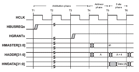
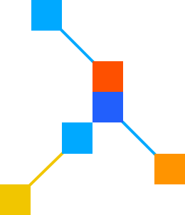
Phase 2: Crossbar Switches Circa the 2000s

As the integration of multiple cores within chips began in the 1990s, too many initiators trying to access different targets simultaneously created bottlenecks on the bus. Latency issues caused by the long amount of time required for arbitration were a major drawback. The industry required concurrent access and more overall system data throughput. A new solution was needed. Crossbars were that solution.

In this case, initiators communicate with targets by means of switches (Figure 2). Once again, each line in this diagram represents a multi-wire bus comprising data, address, and control signals. Any of the initiators can talk to any of the targets. The switches route transactions as they pass from initiator to target and, possibly, back again.

Simple crossbar switch interconnect structure
Figure 2. Simple crossbar switch interconnect structure (Source: Arteris)

The advantage of crossbars is that connections between initiators and targets communicate simultaneously, and multiple transactions can be in flight at any particular time. Arbitration only happens on a per-target basis, significantly reducing arbitration bottlenecks.

However, for initiators that support split transactions, crossbars require complex control logic to keep track of outstanding transactions. Furthermore, as well as signaling for address and control information, they require wide data paths for the initiators and targets that need the most throughput.

As the average number of initiators and targets increased over the years, multiplexers (muxes) for wide buses became impractically large. To support continued system scaling, crossbars started to be cascaded with bridges between fabrics. Bridges between crossbars carried a significant cost in silicon area. They also limited clock frequencies and added significant latency to transactions.

As SoCs grew in size and the addition of IP blocks added complexity, buses, and crossbars revealed their limitations. Shared buses resulted in contention, while hierarchal bus and crossbar architectures created complexity. Throughout the 2000s, initiators and targets became so numerous and widely distributed in the physical floorplan of a chip that crossbars became a physical wiring nightmare. This stood in the way of efficient place and route and timing closure during the backend of SoC design projects.

Phase 3: Network-on-Chip (NoC) Technology Circa the 2010s

Packet-based, serialized NoC technology emerged as a solution to the wiring problem (Figure 3).

The Network Interface Unit (NIU) associated with an initiator IP accepts data from that IP, packetizes and serializes the data, and passes it into the NoC. Similarly, when the packet arrives at its destination, the NIU associated with the target IP deserializes and depacketizes the data before passing it into the IP.

This technology transports address, control, and data information on the same wires, thereby allowing transactions to be sent over smaller numbers of wires while maintaining a high quality of service (QoS) for each transmission.

Simple network-on-chip interconnect architecture.
Figure 3. Simple network-on-chip interconnect architecture. (Source: Arteris)

Distributing the interconnect logic throughout the chip rather than having bridges as chokepoints greatly simplifies floor planning of the most complex chips. NoC technology facilitates a tradeoff between throughput and physical wires at every point within the NoC interconnect network.

NoC Technology Separates the Transaction, Transport, and Physical Layers

Typical interconnect solutions intermingled the transaction, transport, and physical characteristics of the interconnect. This approach has made it difficult to deal with changes to the SoC once the interconnect is completed. Comingling these layers also made it difficult to efficiently implement advanced features like QoS, power domains, clock domains, and security. The introduction of NoCs addressed these issues by separating out the layers.

An example of this advancement is the Arteris NoC interconnect IP. The company is widely acknowledged as the industry leader for state-of-the-art NoC technology.

Better Than Cascaded Crossbars

NoC Transaction Layer

In NoC technology, NIUs manage communication between the NoC and a connected IP core. NIUs convert traditional AMBA, OCP and proprietary protocol load and store transactions into packets for transport across the network. At the periphery of the network, NIUs communicate with the attached IP cores via one of several standard IP sockets, also known as interfaces, or through custom-built sockets to meet specific customer needs.

Most of the interconnect logic resides in NIUs that are close to their respective IP blocks. As a result, fewer gates are required to be placed for the interconnect itself.

NoC Transport Layer

NoC technology enables a transport layer to deal exclusively with packets. Only a limited amount of information in packet headers needs to be examined to determine the required transport operations. The transport layer can safely ignore the specifics of the transactions being managed at its own level. By doing so, the transport layer simplifies the hardware required for switching and routing functions while also enabling higher operating frequencies.

The interconnect topology is made of simple elements that operate independently without global control requirements. Specific packet handling techniques guarantee QoS and bandwidth. Optimization can be performed locally on specific routes without affecting the NoC as a whole.

NoC Physical Layer

The physical layer defines how packets are actually transported between NoC units. Various link types with different capabilities have been employed, such as transport links and globally asynchronous/locally synchronous (GALS) links for longer distances. Having separate transaction and transport layers makes it possible to change links or their characteristics without affecting the other layers.

Additionally, since all connections are point-to-point, high fan-out nets are prevented, resulting in improved performance and easier routing. Compared to prior interconnect implementations, the Arteris NoC interconnect fabric required fewer connections and wires, was easier for chip designers to use, and simplified timing closure.

Cache Memories

Cache memory is a fundamental component of complex SoCs, bridging the speed gap between processors and main memory by storing frequently used data closer to the processor. This improves memory access delays. In cache-coherent systems, consistency is automatically maintained, while non-coherent architectures rely on software or protocols for cache management. In both cases, caches help optimize data access and minimize memory latency.

When a program accesses data from one location in memory, it typically requires access to nearby locations. Furthermore, programs usually feature many nested loops in which multiple operations are performed on the same pieces of data before the program progresses to its next task.

The solution is to have a small, fast memory close to the processor. This memory is called the cache. When the program requests a new piece of data from the main memory, the system automatically retrieves a block of data and loads it into the cache. The processor, usually in the form of a CPU, subsequently performs multiple operations on this local data. Eventually, the new data resulting from these operations is copied back into the main memory.

The CPUs in modern SoCs usually employ multiple levels of cache, with Level 1 (L1) being the closest to the processor, followed by Level 2 (L2) and Level 3 (L3). Each higher-level cache is larger and slower than its predecessor, although still much faster as compared to accesses to main memory.

There can be multiple copies of the same data in the different caches and the main memory. This leads to the concept of cache coherency. If any of the copies are changed, the other copies must be revised to reflect that change. This is a simplified explanation of the concept but illustrates the point.

Coherent NoCs

Cache coherent interconnect enables seamless communication and data sharing between CPUs, GPUs and accelerators, ensuring a unified view of shared memory across the system. By maintaining consistency across multiple processors in hardware, coherent NoCs improve efficiency and simplify software development. Designed for advanced SoC architectures, they support features like distributed cache coherence, making them ideal for high-performance, low-latency applications designed for AI, data centers, and high-performance computing (HPC).

Coherent NoCs are essential in systems where multiple IPs, such as CPU clusters, need to maintain shared memory consistency. If the CPU cluster is required to maintain cache coherence with other IPs, for example, a second CPU cluster, an I/O coherent interface, or accelerator, then a coherent NoC will be employed (Figure 4). In this example, the NoC essentially also acts as a Level 3 (L3) cache.

Examples of coherent NoC deployments
Figure 4. Examples of coherent NoC deployments (Source: Arteris)

Non-Coherent NoCs

A non-coherent NoC is an advanced interconnect IP solution that optimizes SoC development by addressing challenges in performance, power efficiency, and area minimization. The physically-aware design provides early visual feedback, enabling faster timing closure and streamlining the physical layout phase. This approach automates design and verification tasks, reduces development time, and supports tailored topologies to meet the specific needs of each system.

The flexibility in non-coherent NoC designs allows them to be customized for a wide range of SoCarchitectures, from simple single-core implementations to more complex systems. The simplest example is an SoC with a single CPU core (Figure 5a). This processor will maintain coherency between its caches. In this case, the NoC linking the CPU to other IPs in the SoC can be non-coherent if no other IPs contain their own caches or share cached data. If other IPs do have caches, they must be standalone and not need to maintain coherency with the CPU for the NoC to remain non-coherent.

Examples of non-coherent NoC deployments
Figure 5. Examples of non-coherent NoC deployments (Source: Arteris)

Next, let’s consider a cluster of four CPU cores (Figure 5b). One possible deployment is for each core to have its own L1 cache and for all four CPU cores to share an L2 cache.

The CPU cluster will maintain cache coherency within itself. If no other IPs share data with the CPU cluster and therefore do not need to maintain coherency, the NoC linking the CPU cluster to other IPs in the SoC can be non-coherent.

Physically-Aware NoC Technologies

An important feature in non-coherent NoCs is physical-awareness. Previously, the layout and implementation of NoCs were largely performed by hand. Creating constraints associated with the physical placement of NoC elements was an effort-intensive process. This typically resulted in numerous iterations of pipeline insertions and lengthy NoC place-and-route iterations to converge on the SoC’s power, performance, and area (PPA) targets.

Now, NoC technology includes physical awareness, allowing for automatic NoC generation and pipeline stage insertion. Minimizing iterations and providing a correct-by-construction NoC speeds backend physical design. This process leaves the physically optimized NoC IP ready to be handed over to physical synthesis and place-and-route for implementation. Physically aware NoC technology increases productivity and significantly reduces time to market.

SoCs with Non-Coherent + Coherent NoCs

Many SoCs employ multiple NoCs, some coherent and others non-coherent, connected by bridges (Figure 6). Combining both NoCs in an SoC allows designers to allocate resources efficiently, leveraging the strengths of each interconnect type to match specific dataflow requirements. This approach delivers performance optimization, scalability, and system integration, resulting in a balanced and high-performing SoC. Coherent NoCs will primarily manage cached CPUs, while non-coherent NoCs will handle the rest of the SoC interconnect.

SoCs can contain a mixture of non-coherent and coherent NoCs.
Figure 6. SoCs can contain a mixture of non-coherent and coherent NoCs. (Source: Arteris)

Soft Tiling NoC Technologies

NoC soft tiling is an innovative methodology that enhances scalability and modularity in both coherent and non-coherent SoC designs. This approach involves replicating modular units, or soft tiles, within the NoC architecture, each functioning as a self-contained unit to facilitate faster integration, verification, and optimization of SoC designs. This method allows for the seamless scaling of AI-enabled systems by adding soft tiles without disrupting the overall SoC design.

Today’s high-end SoCs may employ an array of processor clusters (PCs) typically connected using a mesh topology coherent NoC, as illustrated in Figure 7a.

Example of a modern high-end SoC
Figure 7. Example of a modern high-end SoC (Source: Arteris)

Similarly, modern NPUs may be composed of arrays of processing elements (PEs), which are typically connected using a mesh topology non-coherent NoC, as illustrated in Figure 7b.

The term programmable units (PUs) embraces both PCs and PEs. The process of generating arrays of PUs has historically been performed by hand. In this case, once the initial PU has been created, it is first replicated, much like copy and paste, into an array of the desired size. Next, a NoC is generated. Finally, the NIUs associated with each of the IPs are customized by hand to give them their unique IDs that the NoC uses to guide packets from initiator to target.

The tasks of replicating the PUs and configuring the NIUs by hand are time-consuming, frustrating, and prone to error. The problem is only exacerbated by the fact that a PU may undergo many changes early in the development cycle, with each change necessitating the re-replication and re-configuration of the PUs and NIUs, respectively.

Arteris has developed a new soft tiling technology that has been seamlessly integrated into its non-coherent and coherent NoC technology (Figure 8).

Generating PU arrays using NoC-based soft tiling technology
Figure 8. Generating PU arrays using NoC-based soft tiling technology (Source: Arteris)

Once the SoC development team has created its initial PU, all that is required is to specify the size of the array, or number of rows and columns, and press the go button. This approach automatically replicates the PUs, generates the NoC, and configures the NIUs with their unique addresses.

Common NoC Topologies

The effectiveness of both coherent and non-coherent NoCs depends on the choice of topology. The term topology refers to the way the individual parts of something are interrelated or arranged. In the context of a NoC, topology describes the specific arrangement and interconnection of nodes, or IPs, within the NoC architecture. This configuration determines how data flows across the SoC and impacts performance, scalability, and efficiency. Different NoC topologies are designed to address various system requirements, including latency, bandwidth, and physical layout constraints.

Note that the crossbar NoC topology is not the same as that of a traditional crossbar implementation. To put this in perspective, the following section explains the key characteristics of and differences between the two.

In a traditional crossbar, each initiator-target pair has a dedicated path, ensuring direct and exclusive communication. The switch relies on physical multiplexers and demultiplexers route data between these pairs. This design allows for simultaneous communication between multiple initiators and targets, maximizing throughput and reducing contention. However, adding more initiators or targets exponentially increases hardware complexity, including greater area requirements, higher power consumption, and increased latency, resulting in diminished scalability.

Compared to traditional crossbars, NoC crossbar topology adopts a fundamentally different approach. Communication is distributed through routers and NIUs, which packetize data and forward it across the network. The interconnect in NoCs is logical, abstracting the direct point-to-point paths and providing greater flexibility. This design allows the topology to scale more effectively, as it avoids the exponential increase in physical hardware that is characteristic of traditional crossbars.

Key differences between traditional crossbars and NoC crossbar topologies are routing mechanisms, scalability, resource efficiency, and applications. Traditional crossbars establish connections through physical switches, while NoC topologies utilize logical routing through packets. In terms of scalability, traditional crossbars become inefficient as the number of nodes increases, but NoCs are better suited for large-scale systems by distributing the interconnect fabric. Resource efficiency is another distinguishing factor.

Traditional crossbars require direct hardware connections for every initiator-target pair, leading to high area and power consumption. In contrast, NoCs manage multiple transactions using shared resources like routers and links. For applications, traditional crossbars are often utilized in smaller-scale systems or for specialized purposes. In comparison, NoC crossbar topologies are common in modern, complex SoCs, where scalability, flexibility, and modularity are essential.

High-level representations of common NoC Topologies
Figure 9. High-level representations of common NoC Topologies (Source: Arteris)

There are several other NoC topology possibilities, which are illustrated in Figure 9. Star topology is a centralized configuration where all nodes are connected to a central hub, ensuring low-latency communication and straightforward routing. This setup works well for small systems with a limited number of nodes but can become a bottleneck as the number of nodes increases, since all traffic must pass through the central hub.

Building on the simplicity of star topology, ring topology arranges nodes in a circular structure, where each node is connected to the next in sequence. This design allows for low-latency communication between nearby nodes but can introduce delays as data travels around the ring in larger systems. Its bandwidth limitations make it less suitable for high-performance applications requiring simultaneous data transfers.

In contrast, tree topology introduces a hierarchical arrangement of nodes, starting from a root node and branching out into multiple levels. This structure facilitates efficient data flow in systems with well-defined hierarchies, such as memory subsystems. However, bottlenecks may occur at higher-level nodes, especially when they handle traffic from numerous lower-level branches.

Moving toward more scalable designs, mesh topology organizes nodes in a grid-like pattern, connecting each node to specific adjacent nodes in rows and columns. This arrangement supports parallel data flows and simplifies routing, which is needed for AI and ML workloads. However, latency can increase as the distance between nodes grows, particularly in large networks.

Extending the scalability of the mesh, torus topology wraps the grid’s edges, connecting nodes at opposite ends to form a closed-loop structure. By reducing the maximum distance between nodes, torus topology enhances load balancing and minimizes latency compared to a standard mesh. However, the additional wiring complexity can make it less practical for smaller systems.

Most modern SoCs employ multiple NoCs with various topologies as required. Some of these NoCs may be standalone, while others will be linked via bridges. As a simple example, a hierarchical tree NoC topology might feature in the main part of the SoC, while a mesh NoC topology may be deployed in an NPU.

In-House NoC Development

Some companies may think that in-house NoC development seems appealing because of its potential customization and control, which allows them to tailor the NoC to meet their specific PPA requirements. It also enables the integration of features that align with their product roadmap. Additionally, in-house solutions can eliminate external dependencies, which some companies perceive as a way to reduce costs.

Developing an in-house NoC comes with significant challenges. Companies must invest heavily in engineering resources, face prolonged development timelines, and constantly adapt to costly, rapid technological advancements. An in-house solution may appear attractive at first, but it typically lacks the configurability, scalability, and maintainability for multiple generations of design. By contrast, commercially developed NoCs offer a streamlined alternative with distinct advantages.

Arteris, for example, brings specialized expertise and experience in designing optimized SoCs that meet stringent performance metrics like PPA, latency, bandwidth, and scalability. The commercial NoC products are rigorously tested and proven in silicon, ensuring reliability. This solution significantly reduces overall development time and costs. Additionally, these NoCs offer configurability to meet specific architectures and topologies, managing diverse processors, multiple IPs, and unique dataflows. Commercial NoCs include robust support and documentation, simplifying integration, and future upgrades. By adopting a proven solution, companies can focus on their core competencies, allocate resources to innovations that differentiate their products, and expedite time to market. 

The Next Generation of NoCs: Scaling for AI, ML, and Beyond

The journey of SoC interconnect technology, evolving from buses to crossbars to NoCs, has been driven by the relentless demand for higher performance, lower power consumption, and greater integration. Today, NoC technology addresses these challenges but also enables SoC designers to push boundaries.

As AI, ML, HPC, and advanced graphics applications continue to dominate semiconductor roadmaps, NoC architectures must evolve further. The exponential growth of heterogeneous computing, with CPUs, GPUs, NPUs, and specialized accelerators collaborating within the same SoC, is driving new demands. Interconnect fabrics must now become more intelligent, adaptable, and physically aware. Trends driving NoC evolution include the following:

  1. AI Workloads and Dataflow Optimization
    Modern AI and ML applications require an immense amount of data movement. Efficient NoC designs must adapt to irregular dataflows, reducing latency and power consumption while maintaining high throughput across distributed processing clusters.
  2. Chiplet Architectures and Advanced Packaging
    Chiplets and 3D packaging are emerging as game-changers. NoC technology must extend beyond monolithic dies to connect disparate chiplets seamlessly, offering uniform QoS and coherent data sharing.
  3. Enhanced Cache Coherence and Memory Sharing
    The need for distributed cache coherence across diverse processing elements will only grow. Future coherent NoCs will need to integrate tighter protocols, smarter arbitration, and dynamic bandwidth allocation.
  4. Security and Reliability
    With increasing complexity, NoCs face heightened threats from side-channel attacks and data integrity challenges. Enhanced NoC IP will include built-in security features such as encryption and robust error correction mechanisms.

The semiconductor industry is in a new era, one where NoCs have evolved from being merely a fabric to becoming the enablers of innovation. Whether driving AI supercomputers or supporting real-time decision-making, NoCs are as critical as the IP blocks they connect. As the demands of the future take shape, NoCs will continue to be the driving force behind the next wave of technological breakthroughs.