Wire Routing Congestion

Don’t overlook the root causes of routing congestion
Arteris network-on-chip interconnect fabric IP allows SoC designers to reduce and remove routing congestion in the architecture phase of design by reducing the number of interconnect wires that will need to be routed.
- What is Routing Congestion?
- Wire Routing Congestion Causes
- Wire Delay RC Delay & Scaling
- How to Eliminate Wire Routing Congestion?
- Arteris FlexNoC Helps Eliminate Wire Routing Congestion
What is Routing Congestion?
 Wire routing congestion occurs on a system-on-chip when a lot of wires (or metal lines) are routed in a narrow space. It becomes prevalent in the on-chip interconnect fabric because it must be routed in the floorplan “white space” between IP block restrictions.
Signal wires suffer the most
Signal wires that carry data are most subject to congestion because they are routed after the power supply and clock wires, and therefore subject to additional constraints. Power supply and clock wires usually occupy the upper-level metal layers where the wires have wider and taller profiles than the mid- and lower-level metal layers. As a result, signal wires are constrained because they must be routed in a manner that accommodates the existing power supply at clock wires.
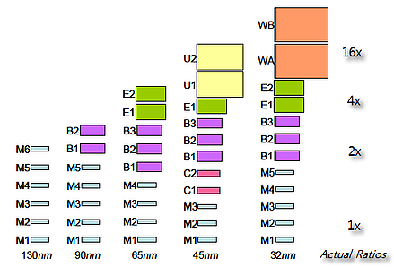 |
| Metal layers grow in size and number with each process node advance Source: C. J. Alpert and G. E. Tellez, “The Importance of Routing Congestion Analysis”, DAC47 |
Measuring routing congestion: G-cells
To perform wire routing, EDA tools divide a system-on-chip into grid cells or “g-cells”. These cells may also be called “bins” or “global routing tiles”. Each g-cell only accommodates a finite number of routing wires.
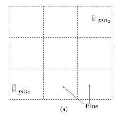 Routing congestion is usually measured as a number with 1.0 being 100% congested, 0.5 being 50% congested and so on. This number is calculated by taking the area of a g-cell and dividing it by the area required to route all the wires wanting to traverse that cell. Note that this wire area includes the width of the wires as well as the dielectric insulation and lateral spaces around the wire to ensure no crosstalk or impedance issues with neighboring wires.
In systems-on-chip, routing congestion is most likely to occur near heavily used IP sockets, like a DRAM memory controller, and near input/output pads and pins.
Wire Routing Congestion Causes
As SoC designs become more complex, routing congestion increases. SoC complexity is enabled by the shrinking sizes of transistors, which creates the following effects:
- More transistors per area allows for a larger and more complex SoC design in the same area as older generation chips. Chip designers take advantage of smaller transistors by packing increasing functionality into each new generation chip, usually by adding blocks of semiconductor intellectual property (IP).
- A larger SoC enables the opportunity to integrate more IP blocks on one chip. The number of wires required for a system on chip grows proportionally to the square of the number of transistors on the chip. The number of IP blocks can be estimated as varying approximately proportionally with the number of transistors.
- In addition to requiring more wires, the cross sectional size of wires connecting IP blocks shrinks less than the size of the transistors.
Wire Resistance & Capacitance Delay (RC Delay) and Wire Scaling
Wires don’t scale as well as the transistors
Wire sizes are not able to shrink at the same rate as transistors. This is because as a wire shrinks, its resistance increases. On average, wire resistance per unit length doubles each process generation, while capacitance stays the same. Assuming transistor scaling of 70% for each process generation change, even though wire length decreases, the delay stays the same. This contrasts with the delays of transistors, which speed up in proportion with the scaling factor with each process generation.
The end result is that the performance benefits of smaller transistors are lost through wire delays.
Need to space wires out more for each new process technology
Also, to handle increasing switching frequencies of each new process technology, wires need to be spaced out more in relation to each other than in previous technologies to reduce capacitance and crosstalk. This means there is no 1:1 scaling even if IP blocks are reused from the old generation to the new generation.
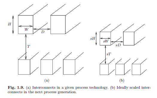 |
| Metal layers do not scale down proportionally to transistor scaling Source: Saxena, Prashant, Shelar, Rupesh S., Sapatnekar, Sachin, “Routing Congestion in VLSI Circuits,” Springer, 2007. |
How to Eliminate Wire Routing Congestion?
Eliminate Wires to Reduce Routing Congestion
A general principle of processes is that increasingly more effort is required to fix problems later in the process flow. For the chip design process, this means that effort avoiding routing congestion in synthesis saves more effort in post-routing engineering change orders (ECOs). This is the purpose of physical synthesis. Furthermore, avoiding routing congestion by reducing the number of wires in the RTL has even more benefit to reducing post-routing timing closure efforts. That is why the higher utilization of a smaller number of wires, as achieved in a network on chip (NoC) interconnect design, is a front end solution to a back end problem.
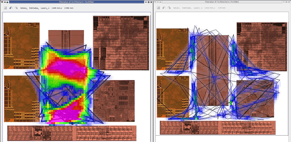 |
| The traditional OCP crossbar on the left has pronounced routing congestion. The same IP with fewer wires due to use of Arteris FlexNoC interconnect IP has no routing congestion. The protocols are OCP for both. Source: Arteris customer design. |
A network-on-chip based interconnect fabric allows architects and designers to easily configure the bit widths of interconnect links based on IP block bandwidth requirements while maintaining their use of the same IP transaction protocols used by the IP blocks. For example, it is common to have many parallel wires for short, high throughput links such as between a CPU and cache, and fewer wires of longer lengths for IP requiring less bandwidth, such as USB and other off-chip peripherals.
For a medium to large system on chip, an Arteris network on chip interconnect typically requires 50% of the wires needed for traditional AMBA multilayered bus and crossbar approaches. In addition to fewer wires, Arteris network on chip interconnects have the following benefits and advantages over traditional AMBA or OCP busses and crossbars:
- Easier timing closure – fine grained pipeline insertion makes it easier to find timing closure issues and fix them without affecting other areas of the chip. And, Arteris FlexNoC IP helps automate this process!
- Easier response to changing IP requirements – Separating the transport from the transaction protocols makes it easy to integrate IP with any transaction protocol into the chip. This “plug and play” capability is especially helpful when there are IP changes late in the development cycle.
- Easier design and modification – A unified toolset with GUI and scripting capabilities allows designers to easily configure interconnects connecting hundreds of IP blocks, simulate the interconnect, output and verify the RTL, and quickly make changes as requirements change.
Arteris FlexNoC Helps Eliminate Wire Routing Congestion
Whether you are using AMBA AXI, OCP, AHB or a proprietary protocol, Arteris Network on Chip (NoC) IP reduces the number of wires by nearly one half, resulting in fewer gates and a more compact chip floor plan. Having the option to configure each connection’s width, and each transaction’s dynamic priority, assures meeting latency and bandwidth requirements. And with the Arteris configuration tool suite, design and verification can be done easily, in a matter of days or even hours.

The Arteris interconnect IP offers us a convenient solution to handle the high speed communication needed between our SoC and external modem IC. Our customers will benefit from the lower BOM cost and power consumption as a result of this IP. We look forward to Arteris’ interconnect IP helping us shorten development schedules and lower risks associated with compatibility.

Thomas Kim, Vice President, SoC Platform Development, System LSI, Samsung Electronics

Arteris FlexNoC 5 Physically Aware Network-on-Chip IP
Watch Now